A “Forced Reset” style trigger allows the operator of the firearm to pull the trigger faster. They are pretty cool, and completely legal.
Recently I decided to design a 3D printed conversion kit that would allow a standard “Mil-Spec” trigger group to be converted to forced reset. The mode of operation is actually very simple, and I was able to make a functional forced reset trigger that used only three 3D printed parts, a pin, and spring. Originally it was my intention to not use any metal parts, but unfortunately that did not work out. The pin is a cut down 3/32″ AR-9 roll pin and the spring is an AR-15 bolt hold open spring. So they are at least common parts.
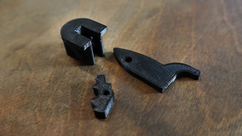
First I want to say that the current design is experimental, I have only spent a couple of days designing and testing so far. There is still a lot of work that needs to be done. The Block that holds the Safety lever is designed to fit into the V2.8 and V3.0 AR-15 Super Lowers, later I will go over how I would like to attach it in the future, but for now keep in mind that the Block only works with the above mentioned 3D printed lowers. Below you can see the parts installed into a V3.0 AR-15 Super Lower printed in Push Plastic Carbon Fiber Nylon. Forced Reset parts are print in Keene Village Plastic Performance PLA.
So how does it work? The operation is actually quite simple. When the bolt cycles to the rear it cams the hammer down, the tail of the hammer then pushes down on the back of the trigger, forcing the trigger and your finger forward. The Safety lever then engages and prevent the trigger from being pulled until the bolt is almost closed, this prevents the hammer from falling onto an open chamber. The result is that your finger is forced forward every time you fire, allowing you to pull the trigger again faster.
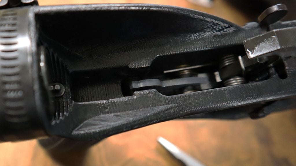
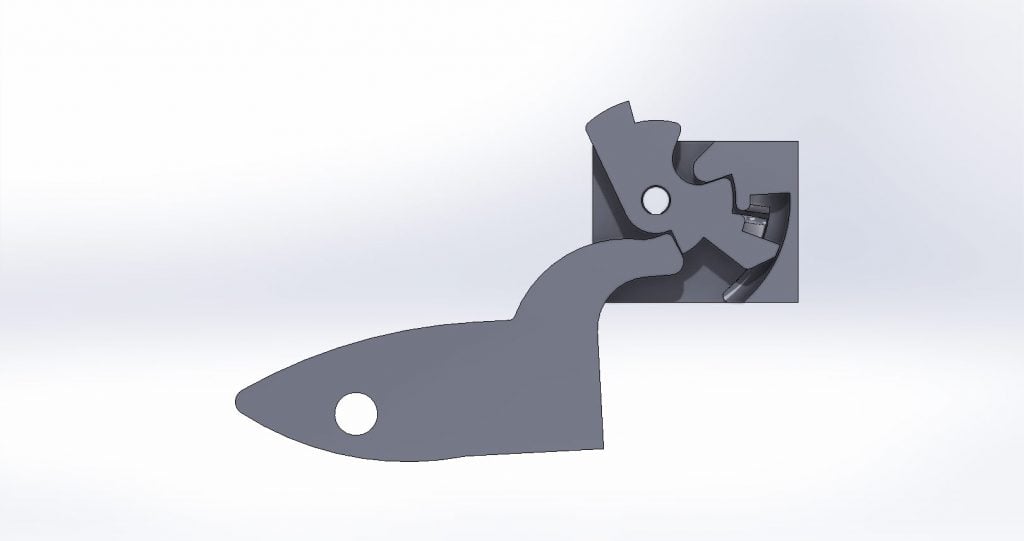
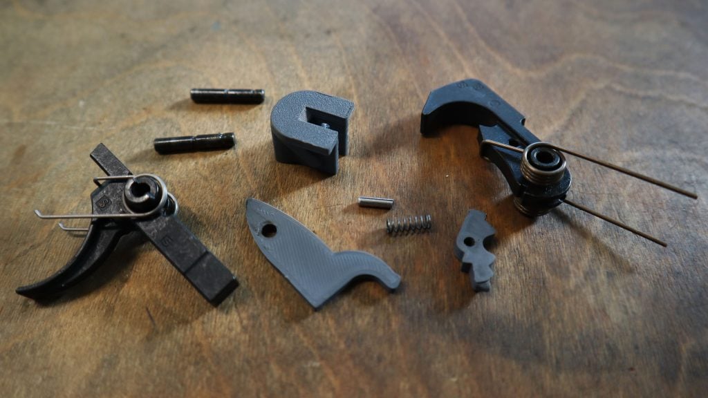
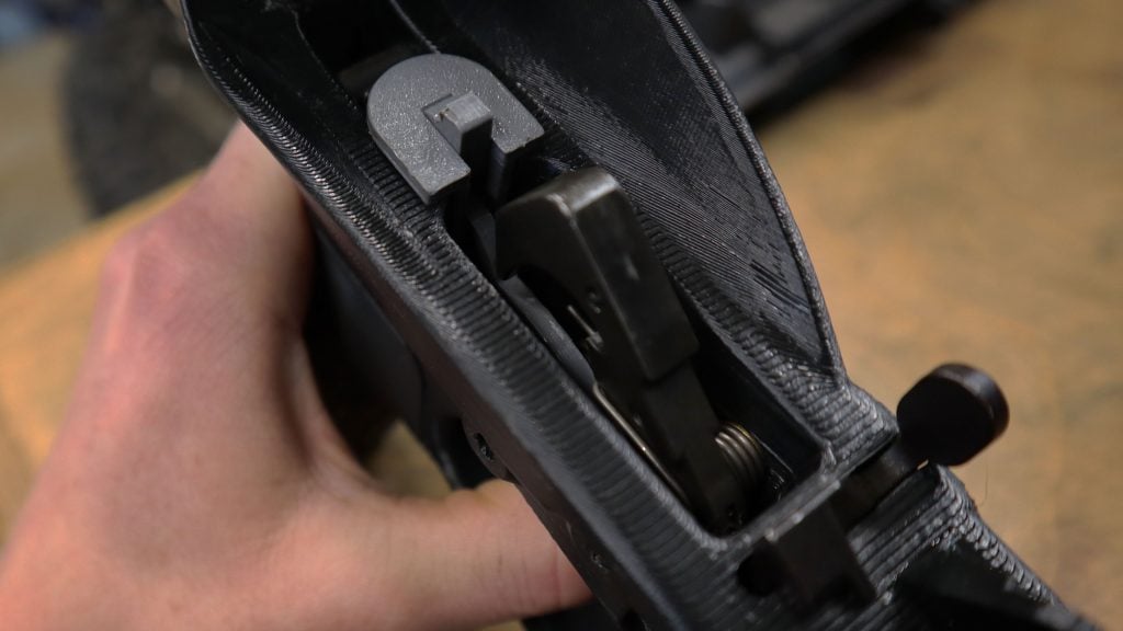
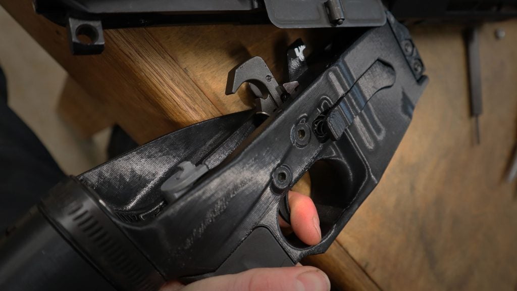
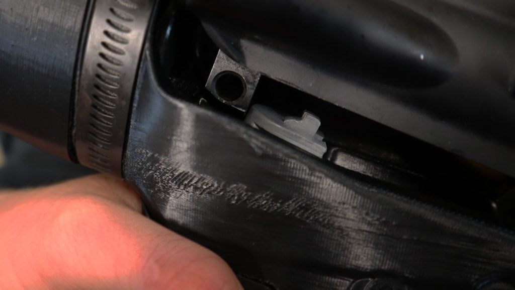
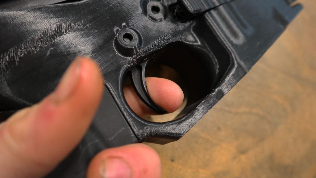
Obviously, in a normal AR-15 fire control group the tail of the hammer does not push down on the rear of the trigger. To achieve this I designed a part I call the “Plate”. It replaces the factory disconnector in the the trigger assembly. It is designed so that when it is installed it can not pivot, basically becoming part of the trigger. This Plate acts as a spacer that the tail of the hammer can push against. It also serves another, equally important, task. The Plate has a tail which curves back and up and over the selector switch drum. This tail is what interacts with the “Safety” lever. Below can be seen the plate installed into a fire control group, as well as a look at all of the 3D printed parts prior to installation, the plate is the part on the left.
Now that you, hopefully, understand the basic function of the trigger, and the purpose of the Plate, I will go over how the Safety lever works and how it is mounted in the lower.
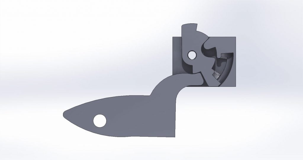
Perhaps the best way to illustrate the operation of the Safety is to show a cross section of the assembly from CAD. Below are two such cross sections. The illustration on the left is when the Safety lever is in the “Locked” position. The trigger is locked open. When the trigger is in this state the bolt carrier is unlocked, and probably has already started moving forward under the force of the buffer spring. Once the bolt carrier is almost closed, the bolt begins to lock. At this time the trip point on the bottom of the bolt carrier contacts the top of the safety lever, moving it forward. The result can be seen in the illustration on the right. When this happens, the the trigger is unlocked and can be pulled to the rear. This results in the tail of the Plate lifting up. This can also be seen in the right illustration. After the trigger is pulled, the weapon cycles again, causing the trigger to be forcefully reset and relocked.
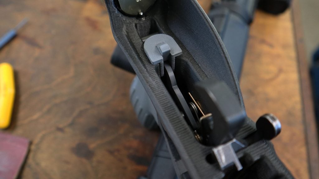
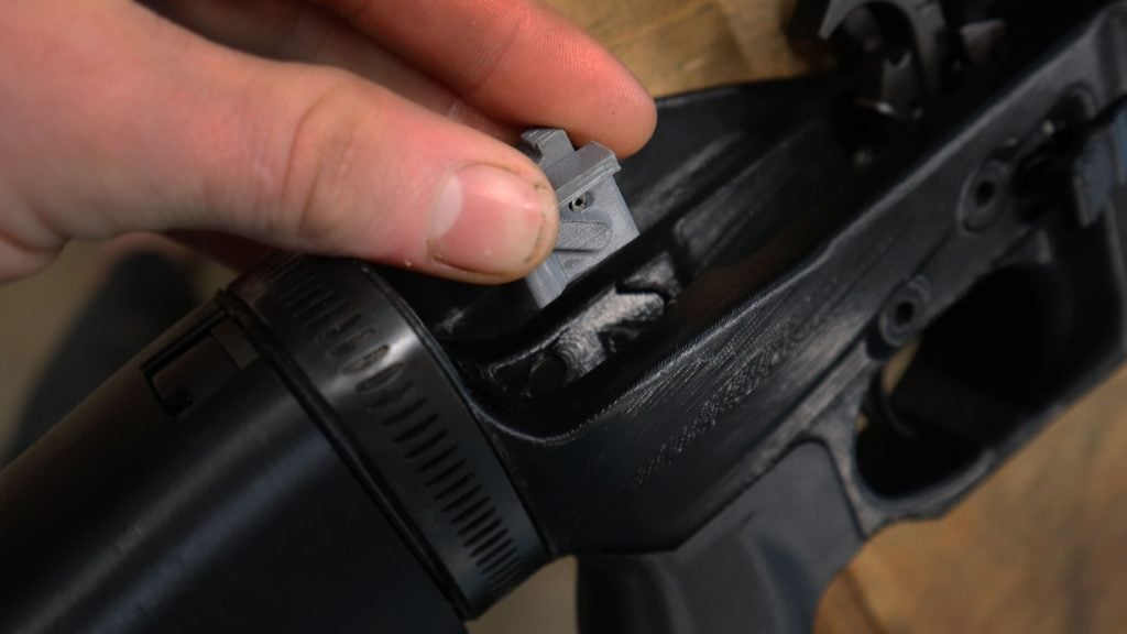
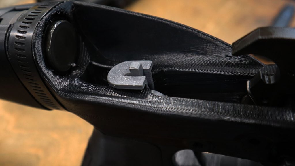
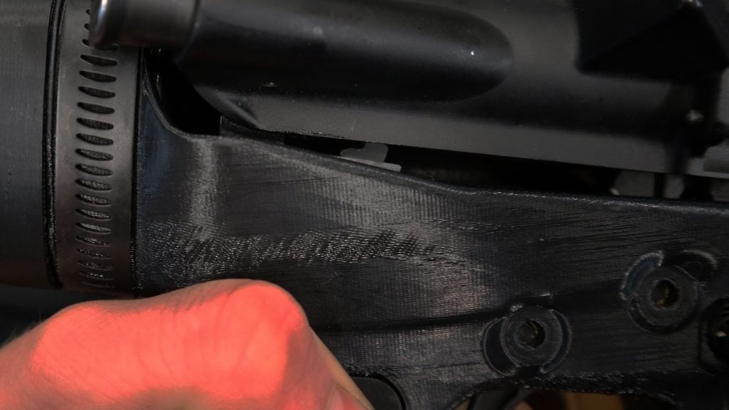
The Safety lever is mounted in a part called the “Block”. The Block is stationary and it’s only purpose is to hold the Safety lever. The current Block design is intended to slide into the rear of the fire control group well on the Super Lower. There are a set of slots that it engages with. These can be seen below. I think this area is where the most improvement can be made. A better Block mount would make assembly easier, as well as make the trigger more reliable with a larger range of uppers.
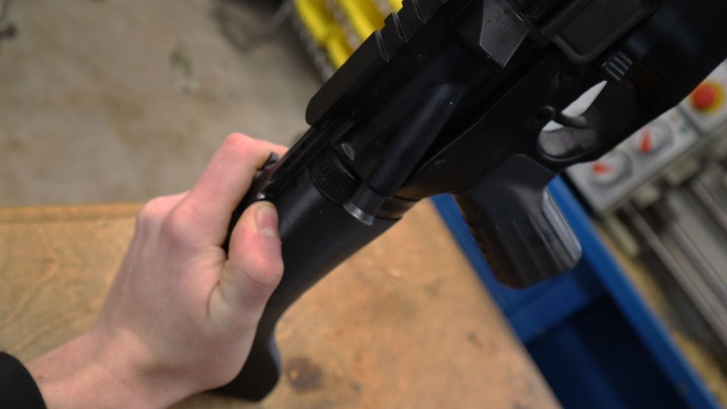
Now, onto the assembly and installation! Below can be seen a complete “Forced Reset” fire control group, less the selector switch. You can see the small spring and roll pin near the center of the photograph. The pin rides in a curved track inside the Block. This track can be seen in the above cut away illustrations. The roll pin is the pivot that supports the Safety.
The first step to converting a standard fire control group to Forced Reset is to remove all of the parts from the fire control group well. This includes the hammer, trigger, disconnector, and selector switch. As well as the pins and springs. Set the disconnector and disconnector spring aside, you will need them to convert back to a standard trigger.
Then reinstall the trigger, with it’s spring, back into the lower. But this time install the Plate in the place of the factory disconnector. It may be difficult to align the trigger pin with the hole in the Plate. A punch can help line the parts up.
Next the hammer and selector can be reinstalled just as they where before. Remember to make sure that all of the pins are fully seated and captured by the springs. The trigger, as far as the lower is concerned, is now fully assembled!
However, you must still assemble the Safety into the Block. You will need a 3/8″ long and 3/32″ diameter roll pin and the spring from an AR-15 bolt hold open. I cut down an AR-9 pin for the roll pin, and you should be able to find the correct spring in your spare parts.
The Safety lever should slide into the block without friction. If needed, sand or file each side of the lever until it fits well. Once this is done, drop the spring into the Block and press it down so that it snaps into the pocket at the end of the curved spring track. Then the Safety can be slid into place, allowing the spring to rest against the small pocket at the end of the Safety lever.
Press the pin through to complete the assembly of the Block and Safety. The last step can be the hardest. Installing the Block into the lower, and then installing the upper onto the lower. Fortunately there is a trick which makes it easy, if you know how.
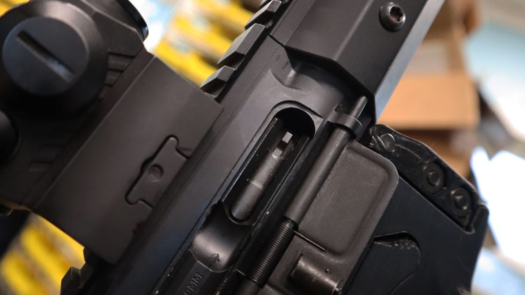
The problem that you can run into is if the Safety lever is in the “Locked” position it will interfere with the bolt carrier. The result of this can be seen below in the left image. The upper will not fully close, and the rear take down pin won’t slide into place. On the right you can see what the Block and Safety look like with out the upper. They look pretty good, everything is lined up and in place. However, this is deceptive.
To begin a proper install, move the hammer into the fallen position. The result is that the Block pops back out of it’s place. This may seem to be counter productive, but it is the right process. Below you can see what this looks like.
Next make sure that the upper is fastened to the lower by the front pivot pin. The next step is critical. Pull the trigger and hold it down firmly. Now you can close the upper onto the lower. You will also have to give the block a little nudge forward to allow the rear take down lug to slide passed the Block. If you try to complete this step without holding the trigger, the Safety lever will tend to pop passed the Plate and move to the locked position. This will cause the above mentioned interference with the bolt carrier, and the upper will not close fully. Holding the trigger prevents the Safety from moving into the locked position.
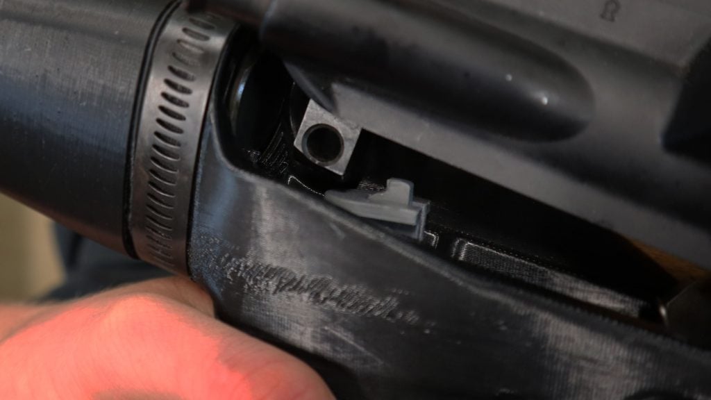
You may have to firmly press the upper and lower together to seat the Block into the upper, but only do this if you are sure that the Safety lever is not interfering with the bolt carrier! Below you can see what it should look like. The Safety is in the forward unlocked position.
If you have trouble pressing in the rear take down pin, try cycling the bolt while holding the upper and lower together. This can help fully seat all the parts. Once the take down pin is in, you are ready do conduct a dry fire test!
To test the trigger, first insure the weapon is empty, and there is no magazine. Then cycle the bolt with your finger off the trigger. The hammer should lock to the rear. When you pull the trigger the hammer should fall. Keep holding the trigger and pull the charging handle to the rear. Your finger should be pushed forward as the trigger is forcefully reset. Now slowly lower the bolt, while still pulling on the trigger. As the bolt locks up, you should feel the trigger unlock as the Safety lever is disengaged. If you are pulling on the trigger when this happens, then the hammer should fall again. You can repeat this process while holding down the trigger, the trigger should unlock and the hammer should fall every time the bolt closes, as long as you hold down the trigger.
You should now be ready for a live fire test. You may need to use a heavy buffer for best results. Just remember, this design is experimental!
O.K. Now we will go over what I think can be improved. The Block is the area that can use the most improvement. Currently it slides into the rails that are designed into the lower receiver. I think these rails should be made vertical instead of at an angle, this will make assembly easier as the block will not pop out when the trigger is dropped. Though I still have to work this out.
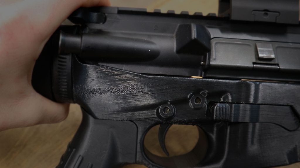
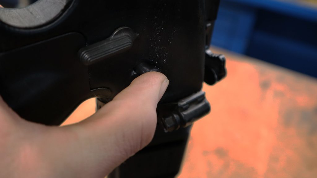
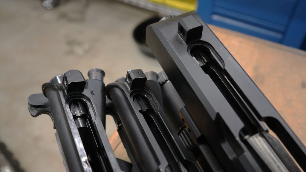
Another problem is how the Block is clamped by the upper. Currently the top of the Block interfaces with a cut that is made in most uppers. The problem is that this cut is not the same on all uppers. And it can even be missing on some. Below you can see the cut on three different uppers, one of them is an LR-308. Instead the top of the block should be wide enough to span this cut and then be held down by the bottom surface of the upper. This way it will work with all uppers.
Lastly, the width of the Safety in the current design is limited to 0.200″ because the Block is only 0.375″ wide. The Block should be made 0.500″ wide to allow for a wider, more reliable, Safety lever.
All of these things will require a new lower design. Once I have it worked out I will update all of my lowers to fit the new Blocks. In fact, I think it would be cool to work with other designers to come up with a “universal” mount for AR-15 fire control group accessories. That way the same accessories could be used in any 3D printed lower.
Another thing that would be interesting is a Block designed to fit aluminum lowers. This is a challenge since there are many variations between different lowers. I think the best option would be to interface with the cut that is shown in the above photo. It’s not a perfect solution, but it would work for a lot of upper / lower combinations.
Something else I want to touch on is using this trigger with an AR-9. I have found that AR-9 bolts have a higher hammer cam surface, so they push the hammer down less. This results in the trigger not being reset far enough for the Safety lever to engage. The solution is a slightly different Plate. I have actually already designed and tested one, and should release it with the next version.
LR-308 lowers also deserve fast triggers. The Safety and Plate will have to be modified, but I think a forced reset 308 rifle is on the horizon!
Of course having a three position selector that would allow you to switch between standard and force reset would be awesome, but I have yet to hit upon a good way of doing this.
I hope you found this post useful! I will be doing a video on this “Forced Reset” Trigger mod soon, so stay tuned!